Create 3d Models from 2d Geographic Data: GIS –> CityEngine –> Vue
This exercise explains how to create detailed 3d models from geographic data utilizing ArcGIS, CityEngine, and Vue software.
The tutorial will cover three main steps:
1. Exporting vector linework (streets) from ArcGIS10
2. Importing line segments into CityEngine, creating models, exporting to Vue
3. Importing models into Vue, adding vegetation and atmosphere (clouds), rendering.
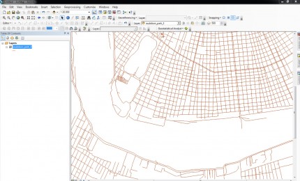
This excercise uses Tiger Files road data for New Orleans, but any vector transporation data will work.
Part 1. Export Shapefile from ArcGIS
1. Load road data into ArcGIS
2. In the Table of Contents, right click the road data layer–> Data–> click Export Data
3. Choose a location and name for the shapefile
Part 2.0 CityEngine: Import
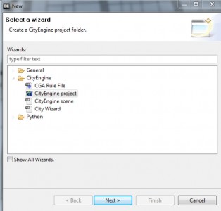
1. Start CityEngine. Click on File, New –> choose CityEngine project
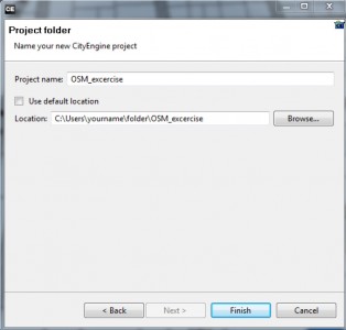
2. Name the project file, choose either the default location or your location of choice, and click Finish
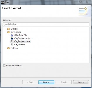
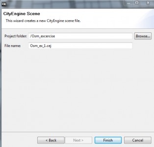
3. Click on File, New –> choose CityEngine scene
4. Name the CityEngine scene, and save it to the default location. The default location is where you saved the CityEngine project. The scenes folder is within the project folder.
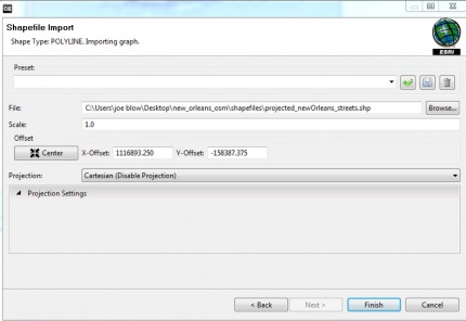
5. Now import the road data shapefile –> File –> Import and choose Shapefile Import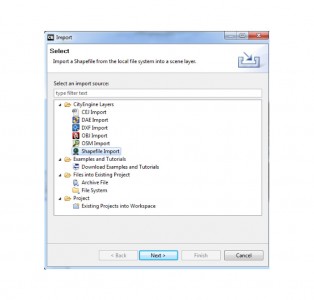
6. In the File parameter, click Browse –> locate the road
data shapefile–> In the Projection dropdown choose, Cartesian(Disable Projection) –> For Offset area, click
“Center” –> click Finish
The road graph network is now imported into CityEngine
Part 2.1 CityEngine: Cleanup Graph Network
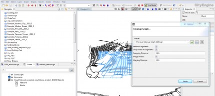
1. First we must clean up the street graph network
–> Make a selection of the graph network in the viewport
–> click Graph on the toolbar–>Clean Up Graph
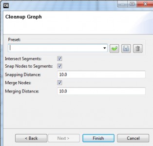
2. Under Graph Cleanup, check the boxes to “Intersect Segments,” “Snap Nodes to Segments,” and “Merge Nodes.” Leave the Snapping Distance and Merging Distance with the default values. Click Finish
3. Once the Graph Cleanup tool is finished, we can proceed to create the road, crossing, and lot shapes that will define our models.
Part 2.2 CityEngine: Shape Creation
1. With the Selection tool (q) select all or a portion of the new street graph network within the viewport.
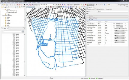
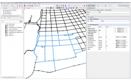
The selection should appear in the Inspector panel(Alt+I for Inspector panel) as three separate data types: Block, Segments, Nodes. Blocks will generate parcel areas, Segments will generate streets, and Nodes will generate street crossings and intersections.
2. Blocks (Parcels): In the Inspector panel –>click on the Blocks tab, and click the black arrow to open the “Block Parameter” rollout.
Each of the rows under the “Name” column control different functions for creating shapes.
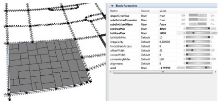
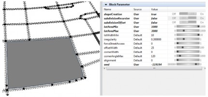
For the Name field titled “shapeCreation,” switch the button to “On” to change the Value field to “true.” This will create our block and lot polygons.
If the “subdivisionRecursive” value is set to “true”, the blocks will be subdivided into multiple lots based on the fields “lotAreaMin” and “lotAreaMax.”
If “subdivisionRecursive” is set to false, then only one large lot will be created.
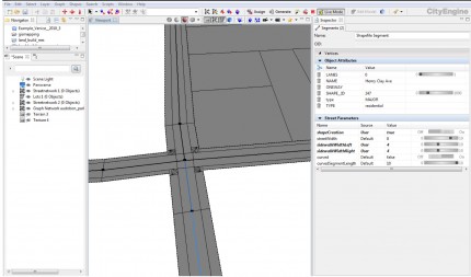
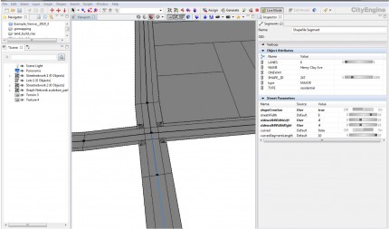
3. Segments (Streets): In the Inspector, click on the Segments tab, and open the “Street Parameter” rollout –>For the Name field titled “shapeCreation,” switch the button to “On” to change the value to “true.”
This will create our street shapes.
Each of the other fields under the Name column control the street shape: streetWidth, sidewalkWidthLeft, sidewalkWidthRight, curved, curvedSegmentLength.
4. Nodes (Crossings): Repeat the previous steps for the Nodes tab within the Inspector. This will create shapes for street crossings and intersections.
5. We can change values in the Street, Block, and Crossing Parameters to manipulate the shapes that are created. Make a selection in the viewport, and change the shape’s Parameter values, observe how the shapes respond parametrically.
We are now ready to apply a CGA Rule file to the shapes to create our models.
Download the Rule file by clicking the link –> Rule File
Replace the “Assets” folder within the CityEngine project with the “Assets” folder from the downloaded zip file. Place the “Building_Streets.cga” rule file in the “Rules” folder within the CE project.
Part 2.3 CityEngine: Generating Models from Shapes
We will start by loading a new Rule File, then applying the rule to the shapes to generate models.
1. Hide the Graph Network and make sure to show Shapes and Models.
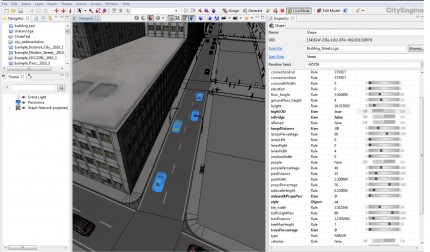
2. For this tutorial we will use a sample rule file to generate our models. This rule file will create simple textured buildings from the lot shapes. The file also contains the Modern Streets rule file from a City Engine tutorial file. The street rule will extrude sidewalks, create crossings and intersections, texture the ground plane, generate light posts, traffic and pedestrians.
3. Now select all or a portion of the shapes to create models.
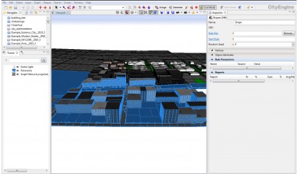
4. With the shapes selected, go to the Inspector tab, click the Browse button –> select the “Buidling_Streets.cga” rule file.
With the rule file selected, click “Generate” at the top of the toolbar.
We will now change some of the rule parameters to create a higher level of detail for the street and building models.
Part 2.3.1 LOD
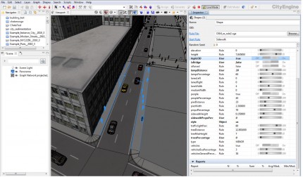
1. Within the CE viewport, make a selection of a road model
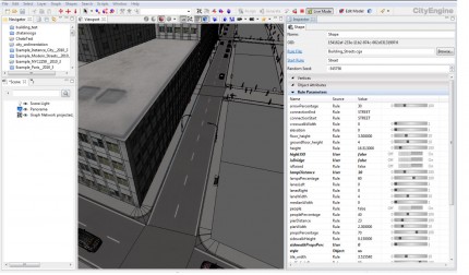
2. Go to the Inspector –> Under Rule Parameters, find the “highLOD” row under the Name field –> change the Value from False to True. This will add cars to the street model
3. In the CE viewport, select both of the sidewalks –>Again,
change the “highLOD” value to true. The sidewalks now have pedestrians, trees, and furniture.
For this exercise, will turn off the tree models–> Find the “treesPercentage” value in the Rule Parameters and change it’s value to zero. We could leave the tree models, but we will add more detailed models in Vue later.
Part 2.4 CityEngine: Exporting Models to Vue
CityEngine has several options for exporting models, but for this exercise we will export the models as a Collada file. CE can export to the native Vue “vob” file format, but we’ll use Collada just in case want to import the file into 3ds Max.
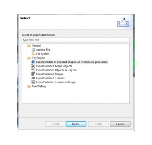
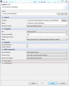
1. Go to File –> Export –> choose “Export Models of Selected Shapes (all models are generated) –> click Next
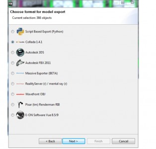
–> Choose Collada 1.4.1 –> click Next
3. In the collada export panel, choose a location and name for the models to be exported.
Under Geometry–> Mesh> choose “Reuse asset instances, merge generated meshes by material.”
Use all of the export settings as pictured in the picture
Click Finish to export the models
In the next step we will import our models in Vue
Part 3.0 Vue: Import, Create, Render
Part three covers file importing, ecosystem creation, atmoshpere creation, and final rendering.
We’ll start by importing the collada file.
File Import
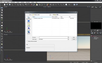
1. Go to File –> Import Object –> choose the model exported from CityEngine, the file extension is “.dae”
–> Click Open
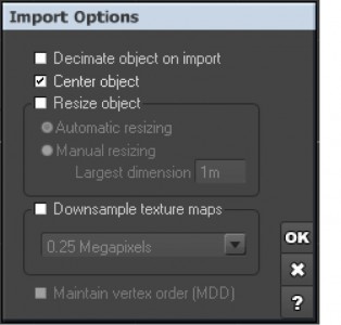
2. In the import options panel –>check Center Object
Part 3.1 Vue: Ecosystem Painting
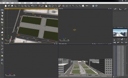
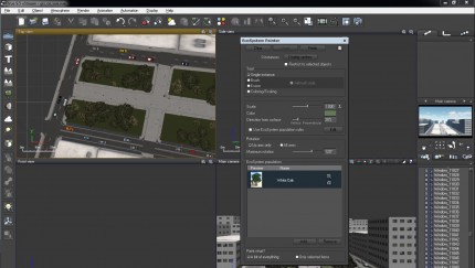
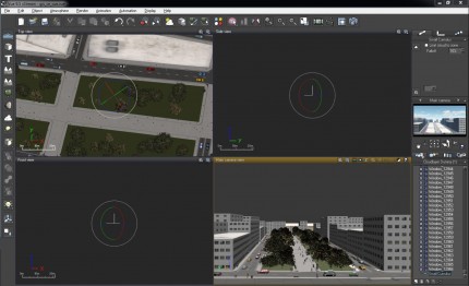
There are many different ways to add vegetation to a scene within Vue, but for this example, we will use the Ecosystem Painter. The picture to the right shows several open lots that will form a greenspace between two streets lined with apartment buildings.
1. In the Top View, zoom in to the location where the Ecosystem trees will be placed
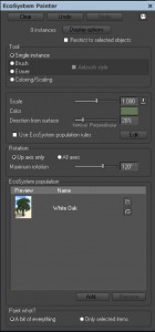
2. Click on the Ecosystem Painter icon
3. Click the Add button at the bottom of the Ecosystem Painter to add vegetation
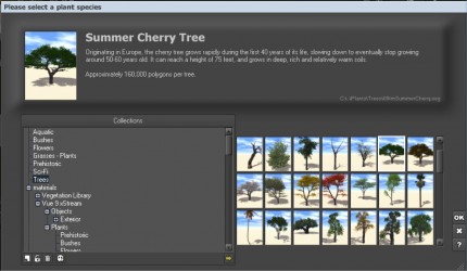
4. Select a tree from the library and click Ok
5. Enable Single instance
6. Click to highlight the tree
7. In the top view, hover your pointer where you’d like to place a tree, and left click with the mouse
In the main camera view, check to see if the tree is to scale. If the tree looks good, move on, otherwise make adjustments to the Scale setting within the Ecosystem Painter
We can also change the Tool settings to “Brush” and paint multiple trees at once.
Other trees and vegetation may be added to the Ecosystem Painter. Using “A bit of everything” will allow us to paint multiple tree species at once.
Part 3.2 Vue: Atmoshpere
We’ll now create clouds and an atmoshphere for the scene
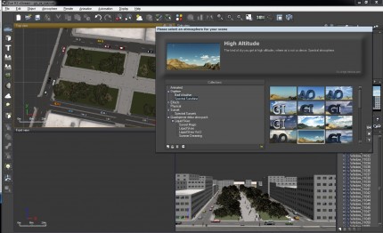
1. Tool bar –> Atmosphere –>click Load Atmosphere
2. Browser through the the different atmospheres and choose one that suits your scene –> click Ok
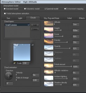
We can make adjustments to the atmosphere and cloud layer in the Atmosphere Editor
3. Tool bar –> Atmosphere –> click Atmosphere Editor
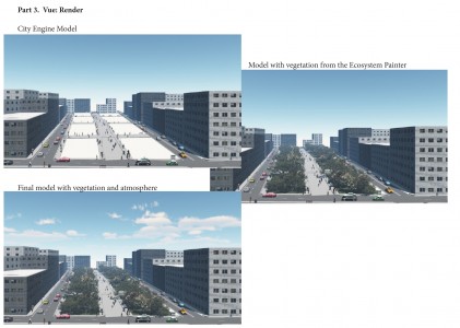
Part 3.3 Vue: Render
Start by positioning the main camera view for the final render shot. Once the view is established you are ready to render the scene
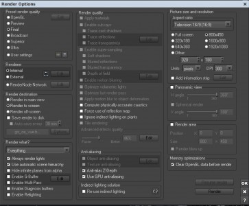
1. Tool bar –> Render –> Render Options
2. Under Preset Render Quality –> Click Final
3. Render Destination –> click Render to screen
4. Adjust the size and DPI of the rendering
5. Click Render

