Create 3d Models from 2d Geographic Data: CityEngine (v10.3) and OpenStreetMap
This exercise explains how to create detailed 3d models from geographic data, utilizing CityEngine software and free open source geographic data from OpenStreetMap (www.openstreetmap.org)
OpenStreetMap is “a free editable map of the whole world. It allows user to view, edit and use geographical data.”
OpenStreetMap can export geographic data that can be used within CityEngine to create detailed models. The OpenStreetMap data will vary from location to location. Some street data may have attributes and values for road width, sidewalk width, number of lanes, etc. and some may not. Each of the data attributes can drive the shape and model creation within CityEngine.
For this example, we will download a street network and bring it into CityEngine. We will create shapes for streets, crossings, and lots, and generate models based on these shapes.
Part 1. Download OpenStreetMap Data
1. Go to www.openstreetmap.org
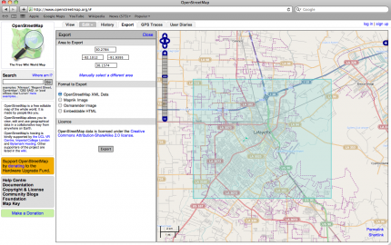
2. Click on the “Export” tab at the top of the page
3. Using the map navigator window, find your area of interest.
4. Under the Export Panel, we will choose “Manually Select a Different Area.” This will allow us to define our area of interest.
5. Under Format to Export, click the button to choose “OpenStreetMap XML Data.”
6. With the mouse, draw a box around the desired area.
7. Click the “Export” button and save the data to an appropriate location.
Part 2. Create a New Project and CityEngine Scene
1. Start CityEngine. Click on File, New –> choose CityEngine project
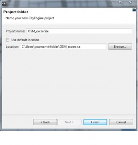
2. Name the project file, choose either the default location or your location of choice, and click Finish
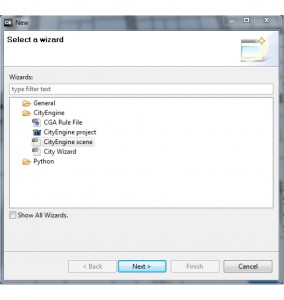
3. Click on File, New –> choose CityEngine scene
4. Name the CityEngine scene, and save it to the default location. The default location is where you saved the CityEngine project. The scenes folder is within the project folder. 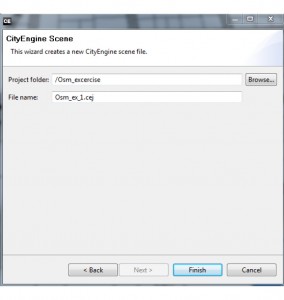
5. Download the sample rule file –> Rule File
–> place the rule file “OSM_excercise.cga” into the Rules folder that is within the newly created CityEngine Projects folder. This file will be used later to generate the CityEngine models.
Part 3. Importing OSM Data into CityEngine
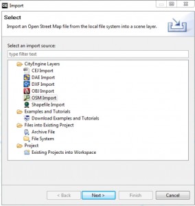
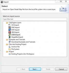
1. Under the File menu, choose Import. In the Import popup box, choose “OSM Import.” Click Next
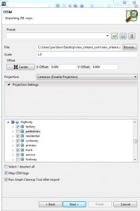
2. The OSM Import popup box will appear. In the File parameter, click Browse –> locate the OSM file (file.osm) that you downloaded earlier. In the Offset area, click Center –> In the Projection dropdown choose, Cartesian(Disable Projection)
3. There are many layers within the OSM file, but we are only interested in the “Highway” layer. Check the box next to “Highway.” For this excercise, disable Pedestrian and Footway if they are available in the list. –> Check the box next to “MapOSM tags”, and “Run Graph Cleanup Tool After Import”–>click Next
–> Click Next again on the Map OSM Tags page
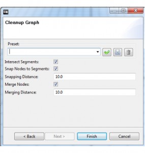
4. Under Graph Cleanup, check the boxes to “Intersect Segments,” “Snap Nodes to Segments,” and “Merge Nodes.” Leave the Snapping Distance and Merging Distance with the default values. Click Finish
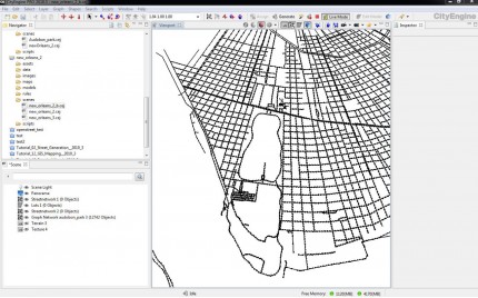
The OSM street data is now imported and ready to use within CityEngine.
Part 4. Create Street and Lot Shapes from OSM Data
(Note that this part of the tutorial is only dealing with the creation of initial shapes. Later the shapes will be used to create actual models. )
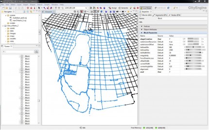
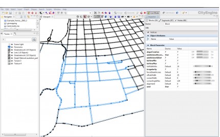
1. With the Selection tool (q) select all or a portion of the new street graph network within the viewport.
The selection should appear in the Inspector panel(Alt+I for Inspector panel) as three separate data types: Block, Segments, Nodes. Blocks will generate parcel areas, Segments will generate streets, and Nodes will generate street crossings and intersections.
2. Blocks (Parcels): In the Inspector panel –>click on the Blocks tab, and click the black arrow to open the “Block Parameter” rollout.
Each of the rows under the “Name” column control different functions for creating shapes.
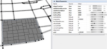
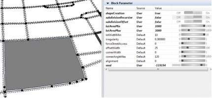
For the Name field “shapeCreation,” switch the button to “On” to change the Value field to “true.” This will create our block and lot polygons.
If the “subdivisionRecursive” value is set to “true”, the blocks will be subdivided into multiple lots based on the fields “lotAreaMin” and “lotAreaMax.”
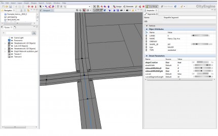
3. Segments (Streets): In the Inspector, click on the Segments tab, and open the “Street Parameter” rollout –>For the Name field “shapeCreation,” switch the button to “On” to change the value to “true.”
This will create our street shapes.
Each of the other fields under the Name column control the street shape: streetWidth, sidewalkWidthLeft, sidewalkWidthRight, curved, curvedSegmentLength.
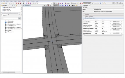
4. Nodes (Crossings): Repeat the previous steps for the Nodes tab within the Inspector. This will create shapes for street crossings and intersections.
5. We can change values in the Street, Block, and Crossing Parameters to manipulate the shapes that are created. Make a selection in the viewport, and change the shape’s Parameter values, observe how the shapes respond parametrically.
Part 5. Generating Models from Shapes
We will start by loading a new Rule File, then applying the rule to the shapes to generate models.
1. Hide the Graph Network and make sure to show Shapes and Models.
2. For this tutorial we will use a sample rule file to generate our models. This rule file will create an offset “green” space within the lots, with a second offset that will extrude a building form. The file also contains the Simple Streets rule file from a City Engine tutorial file. The street rule will extrude sidewalks and create crossings and intersections.
3. Now select all or a portion of the shapes to create models.
4. With the shapes selected, go to the Inspector tab, click the Browse button –> select the “OSM_excercise.cga” rule file.
With the rule file selected, click “Generate” at the top of the toolbar. Our models are now created.

