
Constructing A Flexible Levee System In Grasshopper
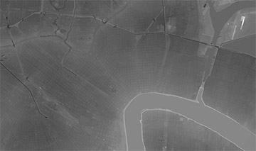
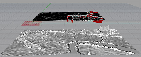
The project contains exaggerated levee systems set within the New Orleans landscape. This exercise manipulates a grasshopper script to allow the levee to gap, rise and fall. Prior to building a script, I brought an Arc GIS, dem file into Rhino. The surface generates the topography from the black and white image by using a heightfield. I repeated this step to create an additional surface and partitioned one of the surfaces into individual meshes. This allows for the manipulation of segments on opposite sides of the levee. These areas would be changing at different rates due to flooding, subsidence and levee breaks/breeches etc.
On the dem surface (not the mesh), trace the levee walls by creating a line using control points to interpolate on the surface. The feature projects the line onto the landscape topography, instead of a flat plane (this doesn’t work on the meshes). To bring the lines onto the mesh surface, copy and align onto levees.
The grasshopper script alters the levee through a series of cylinders. The following instructions create the movable cylinders, the levee.
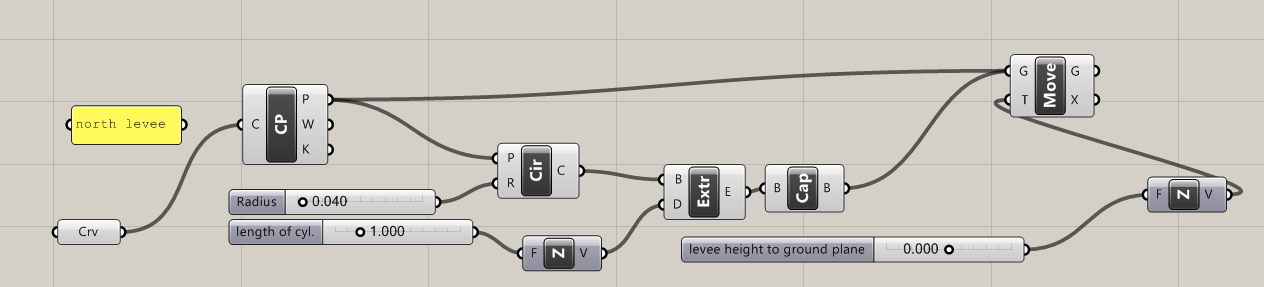
1. Attach traced levee lines to curves in grasshopper. Create the curve button by double left clicking in the blank screen, type “curve”. To attach features from rhino into grasshopper select line in rhino, right click on curve button in grasshopper, and select “set one curve” or “multiple curves” depending on the line/s you’ve selected.
2. Create a control points button. Attach the curve/s button to control points button. This allows for the manipulation of the control points from the rhino line.
3. Create a circle button. Attach “P” from control points button to “P” on circle button. This attaches the center of the circle to the control point. It is important to note the more control points drawn in your Rhino line translates into more circles.
4. The other option on the circle button is “R” or radius. To adjust the size of the circle, create a number slider button. Enter in the desired values. Connect radius number slider in “R” on the circle button. This allows for size adjustment of the base. If the radius is larger, the circles overlap. If the radius is small, gaps form in the levee structure.
5. The circles are lie “flat” along the line, however they will need to be extruded to establish a levee wall. Use the extrude button in grasshopper. Connect the “C” on the circles button to the “B” (base) on the extrude button.
6. “D” on the extrude button refers to the direction of the extrusion. To control this aspect, connect a number slider to a Unit Z button. This connection is saying extrusion of circles will only happen in the z direction. Connect the “V” from Unit Z button to “D” in the extrusion button. Moving the number slider will change the height of the cylinder along the line
7. To enclose the visible portion of each cylinder, make a cap button. Connect the “E” from the extrusion button to the “B” on the cap button.
The two images below display changes in thickness in the red, wireframes and green slider.

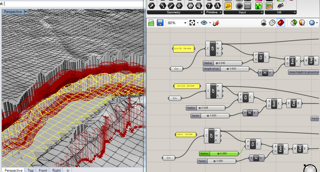
An additional layer was added to move the entire object instead of changing the shape each individual cylinder.
8. Create a move button. Attach control points “P” and Cap “B” to “G” (geometry) on the move button. Create another Z unit button and a number slider to connect with the “T” on the motion button.
Grasshopper has the potential to become a widely used tool for constructing landscapes, however it will need to workout a few glitches. Two of the largest issues with this program are learning the program language and a lack of supplementary teaching materials referencing landscapes.