Procedures for modeling from an AutoCAD file in 3DS Max
Procedures for modeling from an AutoCAD file in 3DS Max:
- Make preliminary decisions about what you are wanting to model in the scene. This can be buildings, planters, paving, grass, water, etc. It’s important that you have an idea of where you want your perspective view so you can be intentional in making these decisions of what to model.
- While you will be modeling in 3ds Max, you will need to prepare an AutoCAD file for importing. Save a copy of your existing AutoCAD file.
AutoCAD Work:
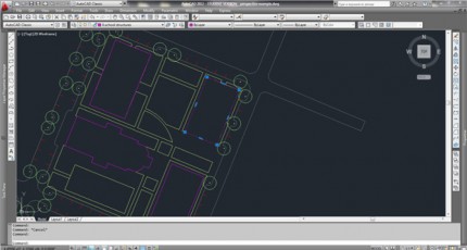
- Open your CAD linework and save it with a different filename
- Each object that you want to model in 3DS should be one continuous polyline.
- Use polyedit (pe) to join existing lines
- OR trace existing lines with a polyline (pl)
- Place objects on appropriate layers in CAD. Delete layer you do not want for your model.
- You are now ready to import your work into 3DSMAX
3dsMax Work:
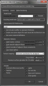
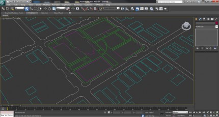
File – import and browse to your CAD file with the linework
- Say yes to the first dialog box
- In the second box, make sure that “weld vertices” is Unchecked. If you created all of your linework using polylines, you won’t need this. Uncheck Auto-smooth adjacent faces and choose Layer under the “Derive AutoCAD Primitives.”
Select your first piece of linework that you want to model
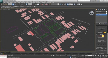
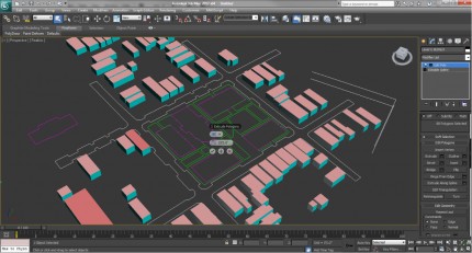
- Under the modify tab, select “edit poly” from the pull-down menu. The object should now have a surface. With this surface, you can apply a material (and leave it as a flat plane) or you can extrude it to create a 3D object.
Extruding geometry
- Enter into sub-object surface mode, either by clicking on the little “+” next to the edit poly and selecting the 4th from the right (looks like a plane), or by simply pressing the number 4.
- When in surface sub object mode, hit crtl+a to select the surface
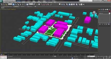
- Under “edit geometry” in the modify panel, there is an “extrude” button. Click the small dialog box next to the “extrude” button and options will appear on your screen next to the object. You can now choose the direction and amount of the extrusion.
Additional Notes:
- Create camera: ctrl+c. Hit P and C to toggle between camera and perspective views.
- Create primitives: under the create panel. You can create boxes, planes, etc. Remember to use your snaps (s) when snapping to linework.
- Add materials: (m) will bring up the material editor. See video tutorial on Moodle.
- Daylight system: create tab, far right “systems”, click daylight system. Click and drag anywhere in the scene to set up the camera. Go the to the modify panel, make sure “mr sun” and “mr sky” are turned on, and under “setup” you can edit location and time.
- Assign renderer: at the bottom of the render setup dialog, make sure mental ray renderer is the default renderer.
- Output size: under render setup, choose custom. Make render size 4800 by 3600.
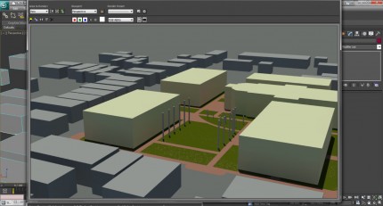
- Render scene: F9 or click the teapot. Remember to save as .tif and check store alpha channel. Render items separately so that they will come into photoshop as different layers.
- Hide unhide selections to render multiple views: Right click on any selection and you can unhide/hide objects. This will enable you to work on individual objects in a clean workspace and also isolate objects to render one at a time.

