LA 2101 : Project 5.0 – Preparing your model for the laser cutter
This tutorial explains how to prepare your file for the laser cutter.
Once you are done with the digital model of your landscape, it is time to prepare your file for the analog model.
- At first you have to decide which components of your digital model you will use to create your analog model.
- Open your file and save it under a different name, since you will delete some geometry
- Select all the objects you do not want the laser cutter to cut out and delete them
- Easy ways to do this is either select by name (h) or freezing your terrain and then drag a selection over the objects you want to delete
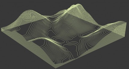
- Now there should only be an editable poly left, representing your terrain
- Make sure, that the bottom of your model is at “0.0” on the “z” axis
- Set your snaps to “vertex” and turn snaps on
- Click on the hierarchy panel and select “Affect Pivot Only”
- Now move the pivot point to one of the vertices at the bottom of your model
- Select your terrain with the move tool and type in a z-value of 0.0
- Now we have to slice our model to create topography-lines, there are two ways of doing this.
- 1.
- Now go to “edge” sub-object mode and click on the “slice plane” button of the edit geometry panel
- A rectangle shows up, indicating the slice plane, by default this plane appears at a z-value of 0.0
- Due to the thickness of a chipboard ply you have to move up the slice plane in certain increments
- These increments are 0.046875″
- With the “move” tool selected move up the slice plane by 0.046875″
- Then hit “slice” just beneath the “slice plane” button to slice your terrain
- Repeat the last two steps until you reached the top of your terrain
- The created topography lines should be selected by default
- Click “create shape” from the “edit edges” roll-out
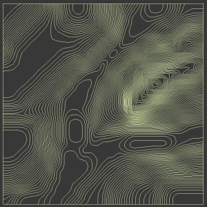
- This will create editable splines from the sliced planes
- You should now be able to select the editable spline and move it away from your terrain model
- Go to “vertex” sub-object mode, hit CTRL+A, right click on your splines and set the vertex type to “corner”
- You should now have an editable spline that looks somehow like this
- 2.
- Now go to the create panel and choose “section” from the “splines” sub-menu
- Create the section at 0,0,0
- A plane should appear
- Toggle on “offset-mode transform” at the bottom of your screen
- From now on you will move up the section plane in 0.047″ increments
- After moving the plane up for one increment, press the create button, type in a name for the new shape
- Repeat these two steps until you reach the top of your terrain
- Put each shape into its own layer. This will make the organization in AutoCAD easier for you
- Now you should export the editable spline to Autocad format
- With the editable spline selected, click on the 3DS Max symbol on the top left of your screen
- Go to “export” and choose “export selected”, pick your file format (.DXF or .DWG), type in the name the file should have and click “save”


[…] Preparing a model for the laser cutter […]